
Knowledge base
Cobalt Sport — User Manual
Installation, operation and maintenance manual for the Cobalt Sport LED stadium perimeter cabinet.
Installation, operation and maintenance manual for the Cobalt Sport 960 × 960 mm LED cabinet.
01 Introduction
Thank you for choosing the Artixium Cobalt Sport. This die-cast aluminium outdoor LED cabinet is designed for stadium perimeters and sports venues. It combines very high brightness, low power consumption, fast heat dissipation and a high protection rating to withstand harsh weather and extreme temperatures.
This manual gathers the information you need to install, operate and maintain your Cobalt Sport perimeter safely: unpacking, assembly, electrical connections, NovaLCT configuration, daily operation, maintenance and troubleshooting. Read it carefully before use to ensure performance and avoid damage or injury.
02 Safety & handling
⚠ Warning: read before installation
This product is for professional use only. Fire, falls or electric shock may cause serious injury or death. Read the instructions below and follow the markings on the product.
2.1 General safety precautions

Installation, operation and maintenance must be carried out by qualified personnel only.
Do not open any cover or modify the product in any way not described in this manual.
Make sure all equipment is in good condition before use.
Cordon off the work area or walkway whenever you install, service or move the product.
2.2 Electrical safety
The product only accepts an AC 100–240 V, 50/60 Hz supply.
The product must be earthed: high leakage currents require proper grounding.
Never use damaged, defective or overheating cables or plugs.
Power and signal cables cannot be repaired: replace them with new ones if damaged.
Switch the power off when the screen is not in use and before any work.
2.3 Handling & transport

Handle cabinets carefully: each cabinet weighs about 32 kg (35 kg/m²).
Use the carrying handles and work in pairs.
When hoisting, assemble from top to bottom and dismantle from bottom to top.
Check that all external masks and hardware are properly locked.
2.4 Installation environment

Operating range: −20 °C to +60 °C, humidity 10% to 95%.
Do not run the screen at full power above 40 °C or below −20 °C.
The Cobalt Sport is rated IP66 front and rear: it is designed for outdoor use.
In windy conditions, add counterweights behind the cabinets (see chapter 05).
2.5 Maintenance & after-sales

Regularly inspect cables, connectors and LED modules.
Do not dismantle power supplies or receiving cards: high voltage hazard.
Only replace faulty parts with Artixium-approved parts.
For repairs, follow the Artixium RMA procedure. Unauthorised repairs may void the warranty.
03 Product overview
3.1 Product description
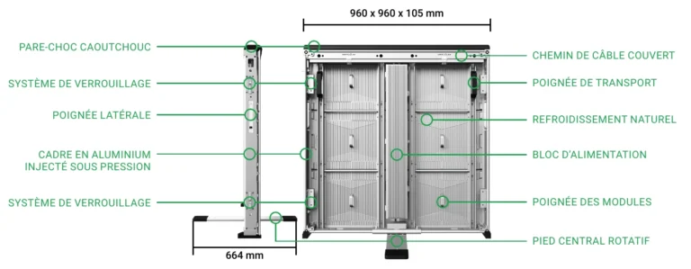
The Cobalt Sport is the stadium perimeter version of our Cobalt outdoor cabinet. It keeps the brightness, quality and durability of the Cobalt LED modules and adds carrying handles, side locks, a rotating central foot and a rubber bumper. It is designed to UEFA requirements and fits dedicated transport carts.
The 960 × 960 mm cabinet is available in P6.6, P8 and P10 pixel pitch, with front and rear maintenance.
3.2 Dimensions
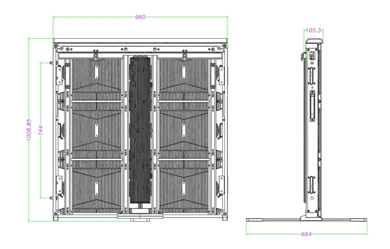
Cabinet: 960 × 960 × 105 mm. Display area: 960 × 960 mm. Central foot footprint: 664 mm.
3.3 Key features
UEFA design: built for stadium perimeters and compatible with dedicated transport carts.
Impact protection: top rubber bumper and soft module masks (rubber masks available as an option).
Protected cabling: power and data cables hidden in a covered, tool-less cable channel, with a built-in leakage protection switch in every cabinet.
Dual maintenance: module access from front and rear, emergency passage design and a rotating central foot to adjust the viewing angle.
Safety: IP66 front and rear and 5VB fire rating.
High brightness: up to 6,000 nits and 3,840 Hz refresh for a clear image in daylight and on camera.
3.4 Main components
3.5 Intended uses
LED perimeters for football, rugby and other sports stadiums
Pitch-side sponsor and advertising display
Indoor or outdoor sports venues
Temporary or permanent ground installations
04 Unpacking & inspection
This chapter explains how to unpack your Cobalt Sport cabinets safely and check that every item is present and in good condition before installation.
4.1 Receiving the delivery
Cabinets are delivered in wooden crates, 6 cabinets per crate (approximate outer dimensions: 1073 × 763 × 1121 mm). Inspect the packaging before signing the delivery note.
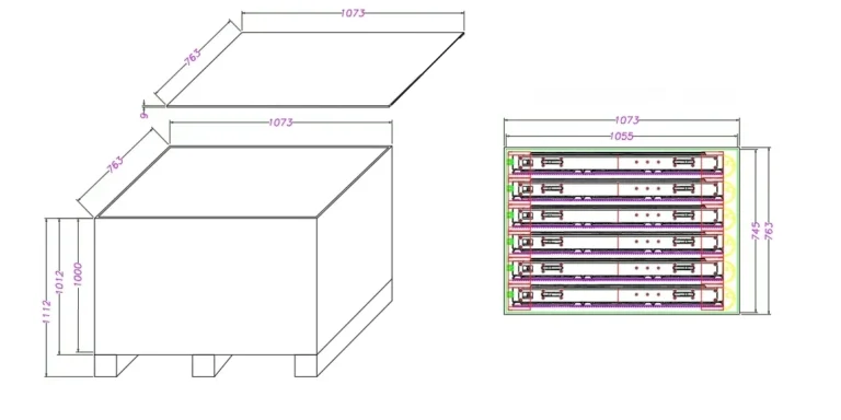
Look for any visible damage (impact, moisture, deformation).
If damaged, note it clearly on the delivery note before accepting the goods.
Inform Artixium or your distributor immediately of any problem.
4.2 Unpacking procedure
Place the crate upright on a flat, stable surface (never on its side or upside down).
Open the crate and remove the protective material.
Lift each cabinet out with two people, using the carrying handles.
Never lay the cabinet LED face down and never press on the modules.
4.3 Package contents
Cobalt Sport LED cabinets
Power and signal cables (depending on the ordered configuration)
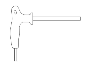
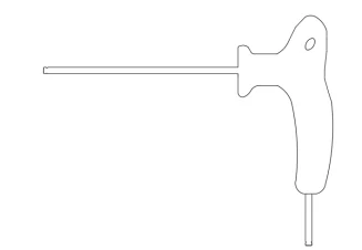
Maintenance tools (M8 Allen key, front maintenance tool)
Edging strips
Spare parts (if included in the order)
Note
Exact contents may vary depending on the project configuration.
4.4 Visual inspection
Check for dead pixels, scratches or damage on the LED surface.
Check the aluminium frame, rotating foot and bumper for damage.
Check connectors, side locks and power box covers.
Make sure all modules are seated and locked.
4.5 What to do in case of a problem
If an item is faulty or missing
Do not install or power the unit.
Take clear photos of the problem and the packaging.
Contact your Artixium representative with the serial numbers.
Follow the official RMA procedure if a replacement or repair is needed.
05 Installation
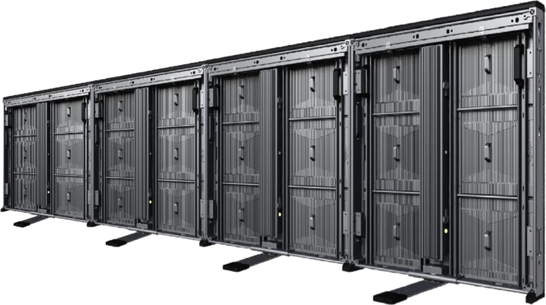
The Cobalt Sport stands on the ground at pitch side on its rotating central foot. Cabinets lock side by side to form a continuous line.
5.1 Installation requirements
Site dimensions match the drawings and all materials meet requirements.
The ground or platform is perfectly flat and level.
Power and signal distribution is prepared in advance.
Installation is carried out by qualified personnel only.
5.2 Required tools
5.3 Assembly steps
Step 1: take out the cabinets and rotate the foot
Take the cabinets out of the flight cases. Rotate the support foot by 90° on the ground to its working position, then line up the cabinets side by side.
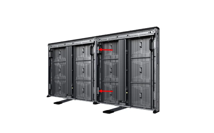
Step 2: lock the cabinets together
Quickly lock two cabinets together with the side locks. Repeat for each cabinet, then tighten with the M8 Allen key while keeping the whole surface level.
Step 3: check flatness
Check the screen is flat and that there are no gaps between cabinets. Adjust if needed: the surface must be flat and seamless, the top edge aligned and all side locks fully tightened.
⚠ Wind stability
In windy conditions, add counterweights behind the cabinets using 50 kg sandbags or similar. We recommend one bag every four cabinets.
Step 4: connect and fit the trims
Connect the power and signal cables according to the diagram supplied by Artixium (chapter 06), then fit the edging strips once the cabinets are secured.
06 Electrical connections
6.1 General electrical safety
Only connect to an earthed AC 100–240 V, 50/60 Hz supply.
The earth must be isolated from neutral and kept away from high-power equipment.
Always work with the power off and follow local electrical regulations.
6.2 Power and signal connection
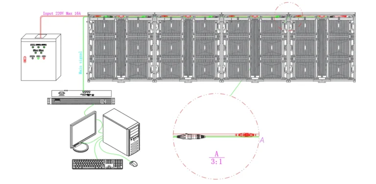
Once the cabinets are assembled, connect the power cables and signal network cables according to the connection diagram supplied by Artixium for your project, cabinet by cabinet, until every cable is connected. Each cabinet has a built-in leakage protection switch.
6.3 Power distribution cabinet (PDC)
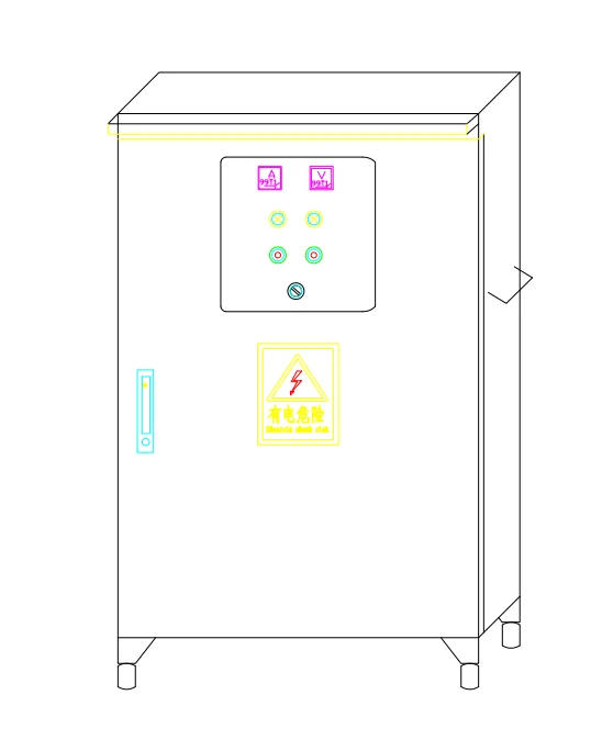
The power distribution cabinet distributes power to the LED display. It monitors temperature, humidity, smoke and supply voltage in real time and can be controlled manually or remotely to check the running status and adjust settings.
6.4 Cable management
Route the cables through the cabinet’s covered cable channel. It closes without tools and protects the cabling while hiding it.
6.5 Power-on check
Check every connection one last time before powering on.
Power on gradually and check the power supply and receiving card indicators.
If anything is abnormal (smell, smoke, flicker), cut the power immediately.
07 Commissioning & configuration
7.1 System overview
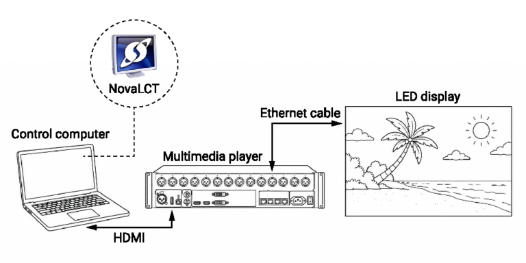
The Cobalt Sport uses NovaStar receiving cards controlled with NovaLCT software. It runs in synchronous mode: the control PC sends the image to the sending card, which passes it to the cabinets over network cable.
7.2 System requirements
Branded PC: i7 processor, 16 GB RAM, 1 TB disk, dedicated 4K graphics card, 23-inch monitor.
Windows 10 or later.
Internet connection required for online calibration.
7.3 Installing NovaLCT
Download NovaLCT from the NovaStar website download centre.
Temporarily disable the antivirus, unzip the package and run the .exe file.
Follow the wizard. If the firewall asks, choose “Allow”: the serial port driver is installed or updated automatically.
7.4 Configuring the screen with NovaLCT
Step 1: connect the PC to the sending card
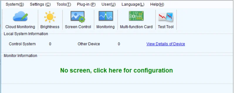
Connect the PC to the sending card with a USB or network cable. When the connection is correct, NovaLCT detects the sending card automatically and shows the monitoring information.
Step 2: log in with advanced access
Choose Login > Synchronize Advanced Login, enter the password and click Login. The default password is given in the NovaStar documentation; remember to change it.
Step 3: load the Artixium configuration file
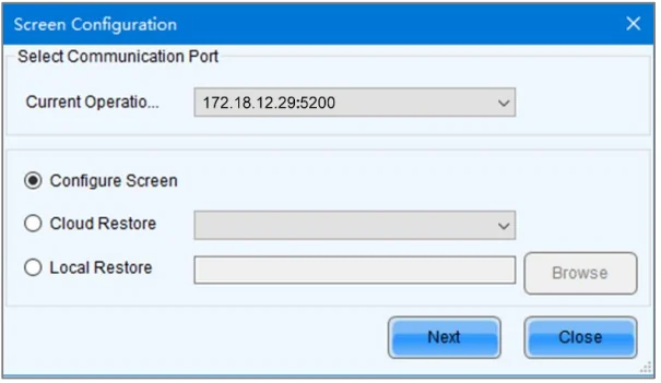
Open Settings > Screen Configuration, select the communication port then Local Restore, and load the configuration file (.scfg or .zip) supplied by Artixium.
Step 4: configure the sending card
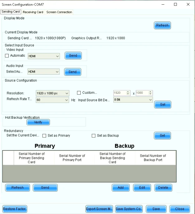
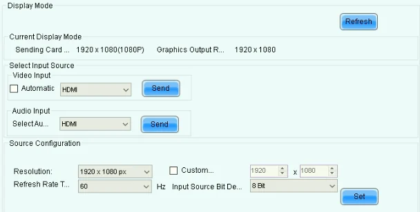
In the Sending Card tab, check the display mode and choose the input source (automatic or manual), resolution, refresh rate and bit depth (8 bit recommended). Click Send, then Refresh to check.
Refresh rate
After changing the refresh rate, resend the performance parameters from the Receiving Card tab so the cards adapt.
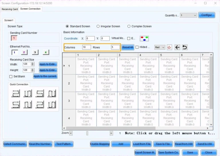
Step 5: configure the screen connection
In the Screen Connection tab, set the number of screens to 1 if the sending card outputs feed the same screen.
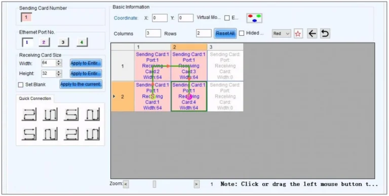
Enter the number of receiving card columns and rows.
Select the output and set the load size of each receiving card.
Click the cards following the actual network cabling order (custom or quick routing).
Step 6: send and save the configuration
Send the configuration to the hardware, then click Save (Cure) once the image is correct to store it in the cards.
7.5 Final commissioning check
The image is complete, correctly positioned and with no offset between cabinets.
No flicker, dark areas or unlit modules.
The configuration is saved in the cards and backed up on the PC.
08 Operation
8.1 Normal operating conditions
Temperature: −20 °C to +60 °C; humidity: 10% to 95%.
Let the screen rest for more than 2 hours a day.
Power the screen on at least once a month for 2 hours. After more than 3 days off, preheat it by raising the brightness gradually.
8.2 Power-on procedure
Switch on the control PC and wait until it runs normally.
Then power on the LED display.
8.3 Good operating practice
Avoid powering on the screen on a full-white, full-brightness image.
Do not display full white at maximum brightness for more than 30 minutes.
Change content every 2–3 hours to avoid ghosting from static images.
If flicker, blackouts or distorted images occur, cut the power and contact a professional. Do not power it on repeatedly.
8.4 Power-off procedure
Switch off the LED display first.
Then close the control software and shut down the PC.
Delay between power cycles
Wait at least 5 minutes between switching the screen off and on again.
09 Maintenance
9.1 General maintenance principles
Always cut the power before any work.
Only use the supplied tools and Artixium-approved parts.
Keep a maintenance log: date, operation and parts replaced.
9.2 Front maintenance
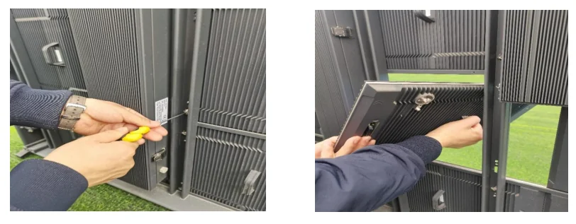
Using the front maintenance tool, turn the mechanical locks at the four corners of the module 90° anticlockwise.
Hold the module, release the safety buckle, then remove it.
9.3 Rear maintenance
Remove the screws connecting the back of the module to the cabinet frame, then turn the four corner locks 90° clockwise.
Grip the module handle, push it forward, rotate it 45° and pull it out diagonally towards the inside.
9.4 Module replacement
Step 1
Take the front maintenance tool matching the module’s pixel pitch.
Step 2
Insert the key into the maintenance holes and turn each of the four corner locks 90° to align the latch with the cabinet opening.
Step 3
Insert two keys into the holes at opposite corners and gently pull the module out to replace it.
9.5 Power supply replacement
From the front
Step 1
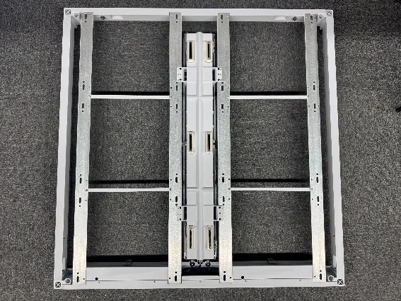
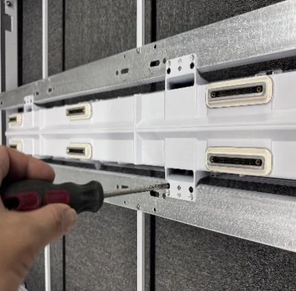
With the modules removed, the fixing plate on the front of the power box is visible.
Step 2
Unscrew the screws that secure the power box to the cabinet frame.
Step 3
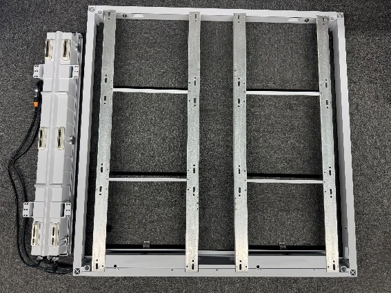
Pull the power box out from the front of the cabinet to replace it.
From the rear
Steps 1 and 2
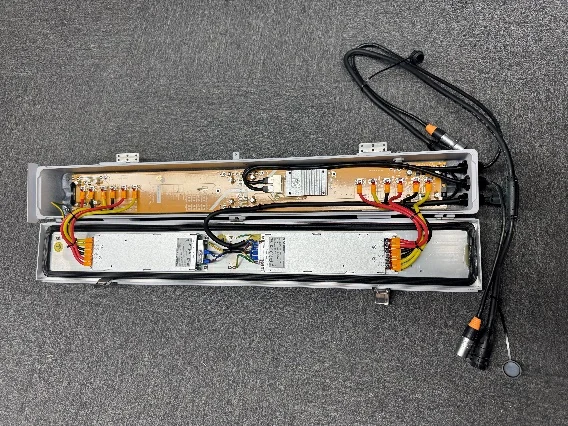
Open the latches and the rear cover of the power box, then remove the screws of the part to replace: HUB card or power supply unit (PSU).
9.6 Receiving card replacement
Steps 1 and 2
Open the latches and the rear cover of the power box, remove the screws of the faulty receiving card and replace it.
9.7 Cleaning
Clean the surface with alcohol, a soft brush or a vacuum cleaner. Never use a wet cloth.
Cleaning every 1–2 months is recommended.
Regularly check that power and signal connectors are tight.
9.8 Preventive maintenance schedule
Frequency | Action |
|---|---|
Before each use | Visual check of the screen, cables and locks |
Every 1–2 months | Surface cleaning and connection check |
Monthly (in storage) | Power on for 30 min to detect dead pixels and dark areas |
Quarterly | Check structural parts for rust |
Yearly | Full inspection by a qualified technician |
9.9 Transport and storage
Transport cabinets packed and upright, protected from wind, rain, sun and corrosive liquids. Do not stack more than three crates.
Storage: −40 °C to +60 °C, 10% to 60% humidity, away from volatile, corrosive or flammable products.
Before long-term storage, unplug and label the cables, store modules upright and protect connectors from moisture.
10 Troubleshooting
10.1 The screen does not light up
Check the power and the power supply indicators.
Check that the sending card green LED is flashing and the graphics card outputs a signal.
Check the receiving card LED and its configuration file.
Check the previous cabinet’s receiving card output or replace the signal cable.
10.2 Misaligned image, noise or flicker
Check the video cable connection (DVI/HDMI).
Check the receiving card configuration file.
Check that the display frequency is set to 60 Hz.
10.3 Some modules in a cabinet stay dark
Check whether the dark area matches one receiving card’s area, and check its LED and input network cable.
Check that the module power connectors are not loose.
10.4 Incomplete or misplaced image
Check that the cabling matches the loaded configuration file.
Check the signal cables between cabinets; replace the receiving card if faulty.
Check that the screen position and size in the software match the real screen.
10.5 Videos do not play
Check that a suitable media player is installed on the PC.
Check that the player supports the file format.
11 RMA & after-sales service
11.1 Reporting a problem
Contact your Artixium representative (website, email or phone) with your contract number or warranty card.
Give the serial number and a detailed description of the problem.
Attach photos or videos if possible.
11.2 Return authorisation (RMA)
No product may be returned without RMA approval.
Include a fault description, a packing list (contract number, model, quantity) and the return shipping details.
Pack the product properly: Artixium is not responsible for damage during return shipping.
11.3 On-site service
Describe the service required.
Give the site address and a local contact.
Provide the information needed for visa applications if applicable.
11.4 Warranty conditions
Customer portal
You can open RMA tickets and track their progress from the Artixium customer portal.
12 Technical specifications
Parameter | P6.6 | P8 | P10 |
|---|---|---|---|
Pixel pitch (mm) | 6.67 | 8.00 | 10.00 |
LED type | SMD2727 | SMD3535 | SMD3535 |
Pixel density (px/m²) | 22,500 | 15,625 | 10,000 |
Cabinet pixel matrix (W × H) | 144 × 144 | 120 × 120 | 96 × 96 |
Module pixel matrix (W × H) | 72 × 48 | 60 × 40 | 48 × 32 |
Application | High-brightness outdoor stadium perimeter | ||
Protection rating | IP66 (front) / IP66 (rear) | ||
Brightness | ≤ 6,000 nits @ 5 V | ||
Colour temperature (adjustable) | 6500 K | ||
Viewing angle (50% brightness) | 180° (±90°) H | ||
Cabinet size (W × H × D) | 960 × 960 × 105 mm | ||
Display area (W × H) | 960 × 960 mm | ||
Module size (W × H × D) | 480 × 320 × 26 mm | ||
Weight | 35 kg/m² | ||
Cabinet material | Die-cast aluminium | ||
Maintenance | Front and rear | ||
Masks | 95% plastic + 5% fibre / stainless screws / louvres | ||
Contrast ratio | High | ||
Grey scale (linear) | 16 bit | ||
Brightness control | 16 bit | ||
Processing depth | 16 bit | ||
Colours | 281 trillion | ||
Refresh rate | 3840 Hz | ||
Power supply | AC 85–230 V | ||
Max. power consumption | 550 W/m² | ||
Average power consumption | 200 W/m² | ||
Control mode | Synchronous | ||
Video frame rate | 50 / 60 Hz | ||
Supported inputs | DVI / SDI / HDMI | ||
3D ready (optional) | Yes | ||
Calibration | Yes | ||
Lifetime (50% brightness) | 50,000 h | ||
Operating humidity | 10 – 95% | ||
Operating temperature | −20 °C / +60 °C | ||
Options | Rubber masks | ||
Certification | EMC Class B / CE / ETL / CCC | ||
13 Compliance & warranty
13.1 Certifications
The Cobalt Sport complies with the applicable international standards: CE, ETL, CCC and EMC Class B.
13.2 Warranty coverage
Standard warranty period defined by the contract.
Covers manufacturing and component defects.
Assumes installation and use in line with this manual.
13.3 Limitations
The warranty does not cover:
Consumables (connectors, fibres, cables, etc.) unless agreed in writing.
Improper handling, installation, dismantling or transport.
Dismantling, repairs or modifications not authorised by Artixium.
Accidental or physical damage, or damage caused by misuse.
Force majeure (lightning, flood, fire, etc.).
Storage or use outside specifications (voltage, climate, salt spray, etc.).
Natural brightness loss over time or lack of maintenance.
Altered serial numbers or warranty documents.
Related articles
A10s Plus — Datasheet
Official NovaStar datasheet for the A10s Plus, in PDF format. Artixium supplies and configures this equipment with its LED displays.
A10s PRO — Datasheet
Official NovaStar datasheet for the A10s PRO, in PDF format. Artixium supplies and configures this equipment with its LED displays.
A4S — Datasheet
Official NovaStar datasheet for the A4S, in PDF format. Artixium supplies and configures this equipment with its LED displays.